Mesh Pop-Up Menu
A pop-up menu is available in the Data Settings and Properties to provide access tools for smoothing meshes, creating deviation maps, and managing scalar information, as well as for exporting meshes and executing macros. You should note that the items available in the pop-menu are dependent on the number of meshes selected — one or multiple.
The following items are available when you select a single mesh in the Data Properties and Settings panel.
Opens the Measurement Inspector panel (see Evaluating Meshes with the Measurement Inspector).
NOTE Available only for meshes with scalar values.
Lets you save the selected mesh in a number of different file formats suitable for 3D printing and other purposes (see Exporting Meshes).
Lets you save the selected mesh in the ORSObject file format (*.ORSObject extension). See Exporting Objects.
Provides a shortcut for selecting macros that can be executed for the selected mesh (see Recording and Playing Macros).
Opens the Mesh Decimator panel, in which you can reduce the number of vertices, edges, and triangles in a mesh (see Decimating Meshes).
Opens the Mesh Smoothing panel, in which you can smooth meshes with a selected method and number of iterations (see Smoothing Meshes).
Opens the Mesh Subdivider panel, in which you can increase the resolution of the selected mesh by dividing its triangles into smaller units (see Subdividing Meshes).
Opens the Mesh Registration panel, in which you can register a selected mesh with a reference (see Registering Meshes).
Calculates the deviation (distance) between two sets of meshes and shows the error as a colored map on the mesh surfaces (see Generating Deviation Maps).
Calculates the deviation (distance) between two sets of meshes and shows the error as a colored map on the mesh surfaces (see Generating Deviation Maps).
Lets you compute the number of non-manifold edges in a selected mesh. This function can be used to verify that a mesh does not contain any edges with more than two faces attached to it. You can use this option to evaluate the integrity of a mesh that will be used for 3D printing.
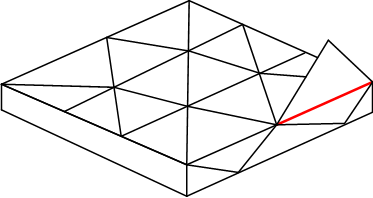
As shown in the example below, non-manifold topology polygons have a configuration that cannot be unfolded into a continuous flat piece. This condition, in which more than two faces share an edge, is known as multiply connected geometry.
Non-manifold edge (in red)
- Right-click the mesh you need to analyze and then choose Get Non Manifold Edges Count in the pop-up menu.
The results are computed automatically and appear in the Mesh Information dialog, shown below.
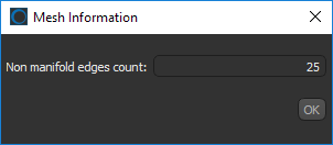
You should note that a value of 0 indicates that the mesh does not contain any non real-world geometry.
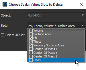
Lets you delete selected measurements from scalar meshes (see Scalar Information). You can select multiple scalar value slots when deleting scalar information, as shown below.
Lets you import scalar values contained in a selected comma-separated values file (*.CSV extension). You can import scalar values from either an ORS-formatted CSV file, in which case all slots will be imported, or you can import scalar values from a generic CSV file that contains the required IDs and corresponding values.
The options for importing scalar values from a generic CSV file are available in the Scalar Values Slots Importer dialog, shown below.
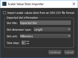
NOTE ORS-formatted CSV files are formatted in columns as follows: | Object-Name | Time Step | ID | Unit | Value |, in which the ID can be a vertex, edge, or face for meshes and a label for multi-ROIs. Generic CSV files must be formatted as: | ID | Value |. Other information, such as slot title can be entered manually.
Lets you map selected measurements contained within a scalar mesh to another mesh or multi-ROI (see Scalar Information).
NOTE This options is available only for meshes with scalar values.
Lets you copy selected measurements contained within a scalar mesh to another mesh (see Scalar Information).
Available only for meshes with scalar values.
Automatically aligns the centroid of the selected mesh with the centroid of another object. Other applicable objects include volumetric image data, regions of interest, and meshes. These objects can be selected in Choose the object to align with dialog, as shown below.
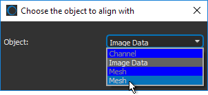
Lets you apply simple transformations to the selected mesh, such as translations and rotations, that were applied to another object. You should note that only objects that were translated and/or rotated, will be available in the Choose an object dialog, as shown below.
![]()
Copies the selected mesh. Copied meshes will appear as new items in the Data Properties and Settings panel.
Automatically creates a box that corresponds to the dimensions of the selected mesh.
The following items are available whenever you select two or more meshes in the Data Properties and Settings panel.
Exports the selected items in the ORS Object file format (*.ORSObject extension) to a selected folder as multiple files (see Exporting Objects).
If the selected meshes share the same name, their file names will be appended with a sequential number.
Exports the selected items to an ORS Object File (*.ORSObject extension) to a selected folder (see Exporting Objects).
Provides a shortcut for selecting macros that can be executed for the number of items selected.